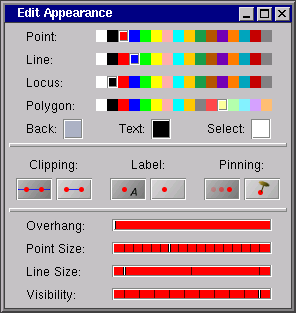
The Appearance Editor is a window in which you can control the graphical appearance of elements in the construction. Changes always refer to the selected elements. Any changes made in the appearance are instantly passed to the views.
The settings in the appearance panel also serve a second purpose. They are taken as default settings for any newly added elements. This means newly added elements get the appearance that corresponds to the settings in the Appearance Editor.
The attributes that you can control with the appearance editor are the following:

|
| The Appearance Editor Window. |
The colors of the geometric elements are organized as follows. The geometric elements are grouped into four different types:
For each of these groups the Appearance Editor offers a palette of 16 different default colors.

|
| Color palettes for the elements. |
In each palette one entry is marked. This is the current default for this group. You can change this mark by clicking on another entry. So, if you want to change the color of a point from red to green, you have to do the following:
You can also change the appearance of several points at the same time if you select more than one point. After your change has been performed the green color is the new default for added points. A similar procedure applies to the other three color groups.
It may be the case that you are not satisfied with the color choices offered by Cinderella. You can change the a color value by double-clicking on its entry in the color palette. A color chooser window pops up in which you can adjust the red/green/blue values of the palette entry.

|
| Color Chooser |
It is important to know that by changing the color of an entry in the palette you change the color of all geometric elements associated with this color entry.
Currently the palette is not stored with the configuration in the ".cdy" file.
There are three other entries in the Appearance Editor that control colors.
| View Colors |
These entries refer to the default colors for the views.
These settings apply to all views. Make sure that the three colors are clearly distinguishable from each other.
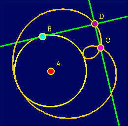
|
| Example of an individualized color map |
You can control whether a line is "clipped" or not. For this purpose the Appearance Editor offers two buttons that turn clipping on or off.

|
| Clipping choice |
A non-clipped line will be drawn over the whole size of a view. A clipped line is truncated with respect to the points lying on it. The rules that govern the clipping logic are a bit intricate, but they lead to natural behavior:
This is what you would expect for geometric drawings. The decision of whether a point is (always) incident to a line is done by the automatic theorem checking of Cinderella. In this way a correct and mathematically consistent behavior is ensured.
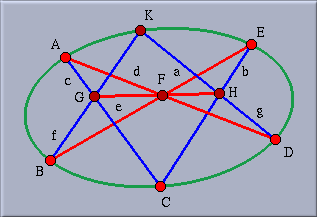
|
| Pascal's Theorem with clipping |
Every geometric element has a flag to indicate whether its label should be shown or not. This can be controlled by the Label choice:

|
| Label choice |
So far the display of labels in geometric views is only provided for points and for lines. If you want to label conics or loci you can place a point of size zero near them. This point serves as a carrier for the label.
Pinning describes the behavior, not the appearance of an element. If a movable element (e.g., a free point) is "pinned" then it is no longer movable.

|
| Pinning choice |
This feature is necessary to restrict the freedom of an element in a drawing and can be useful when you design exercises.
The following types of elements are movable and can therefore be pinned.
It is often not desirable to have a clipped line end directly at some points. It looks much nicer to have some overhang that suggests that the line continues further. You can control the size of an overhang by using the overhang slider. The slider's position adjusts the overhang on both sides between 0% and 50% of the line's total length.
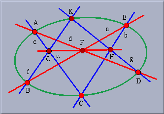
|
| Pascal's Theorem with clipping and overhang |
To control the size of objects there are two sliders in the Appearance Editor. One slider controls the size of point elements.

|
| Possible point sizes |
Points of size zero are very useful objects. They are invisible, but they are selectable and movable and they still serve as active clipping points for clipping lines. This makes them ideal elements to use when you want to have a line that you can move by grabbing its endpoints. So you do not have to make unnecessary "decorations" with visible points.
|
| Possible line sizes |
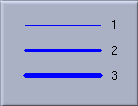
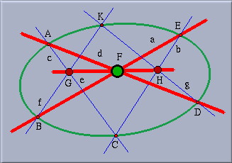
The other slider controls the thickness of line-like elements (between 1 and 3). "Line-like elements" are lines, circles, conics and loci.
|
| Pascal's Theorem with points and lines of different sizes. |
The Appearance Editor has a slider for adjusting the opaqueness of elements. The opaqueness can vary from "absolutely invisible" to "solid".
| Grades of opaqueness. |
Absolutely invisible elements are good for auxiliary constructions that should not be disturb the rest of the drawing. Slightly visible elements can be used for parts of a construction that are of minor importance. For an element to take active part in the views (being movable and selectable) it needs a opaqueness of at least 20 percent. You can select invisible elements in the textual view. They cannot, however, be used for clipping lines.