In the second tutorial we want to explore the dynamics of a little mechanical linkage. In particular, you will learn how to make bars of a fixed length. You will also learn how to produce a geometric locus of a point.
After starting Cinderella or after erasing your previous
configuration you switch to the
"Add circle by radius" mode by
pressing the button ![]() .
This mode is used for circles whose radii remains constant when
their centers move. Move the mouse pointer over
the view. Press the left mouse button.
Hold the button while dragging the mouse. Release the mouse.
With these actions you generated a circle. Switch to the move mode to
see how the circle behaves. When you pick the center you can
move the position of the circle while the radius stays
constant. You can also pick the circle itself and
move it. Then its center stays fixed and the radius of the
circle changes.
.
This mode is used for circles whose radii remains constant when
their centers move. Move the mouse pointer over
the view. Press the left mouse button.
Hold the button while dragging the mouse. Release the mouse.
With these actions you generated a circle. Switch to the move mode to
see how the circle behaves. When you pick the center you can
move the position of the circle while the radius stays
constant. You can also pick the circle itself and
move it. Then its center stays fixed and the radius of the
circle changes.
 |
| Fig. 1: A first circle |
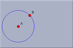
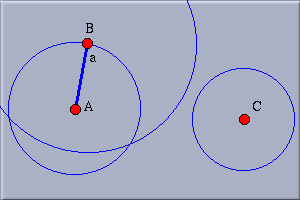
We now want to add a point that is bound to the boundary of the circle. Select the "Add a point" mode. Move the mouse over the view. With the button pressed move the mouse pointer to the boundary of the circle. When the circle is highlighted, release the mouse. You have now created a point that is on the boundary of the circle. You could alternatively have clicked the mouse over the circle boundary. However, in this way you have a bit less control on whether you actually hit the circle. Your configuration should now look approximately like that in Figure 1.
Switch to the "Move" mode to see how this new point behaves. If you pick it and drag the mouse it will never leave the circle. Under this restriction it tries to be as close to the mouse position as possible. When you move the center of the circle, or change the circle's radius, the point also stays on the circle. The point furthermore keeps its relative angle to the center.
Choose the interactive "Add a line" mode and draw a line
from the center to the perimeter point. Open the Appearance
Editor. Select the line and clip it by pressing the
![]() button in the Appearance Editor
window (see Figure 2).
button in the Appearance Editor
window (see Figure 2).
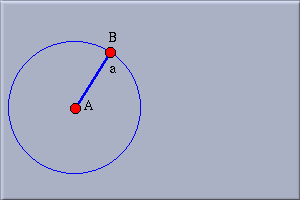 |
| Fig. 2: A bar |
This line now behaves like a bar of fixed length, which is given by the radius of the circle. The only way to change its length is to change the radius of the circle.
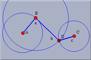
We now want to add two more bars to complete the three-bar-linkage that you have seen in Section 2.1.2 of the introduction. The linkage is a chain of three consecutive bars which should be pinned down at both of its ends. Switch to the "Add a circle by radius" mode again and add a second circle right to the first one. Do not let the two circles intersect.
The radius of the second circle represents the length of the third bar in the row (we have not created the second one, though). To finish the construction it is worth analyzing the situation. If point C in our construction should be linked to point B of the construction by two bars of given lengths, then there is not much freedom for the point that is common to these two bars. Actually, there are exactly two positions for this point. They are the two intersections of two circles: one circle around C, already drawn, and another circle around B.
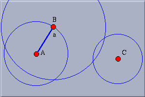 |
| Fig. 3: Another two circles |
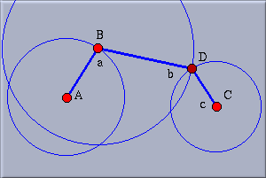
So, as a next step draw a circle around B in the "Add a circle by radius" mode. Make sure that its radius is large enough so the circle also intersects the circle around C. This stage of the construction is shown in Figure 3. Finally, draw a line with the "Add a line" mode from B to one of the intersections of the circle around B and the circle around C.
 |
| Fig. 4: All three bars |
This new point is automatically labelled D. Notice that this point is not a free point, since it position is determined, up to choosing the second intersection, by the positions of A, B, and C, and the radii of our circle.
Finish the construction by adding the third bar from C to D. Most probably the lines are already clipped, since you made this choice in the Appearance Editor. If not, select them and use the Appearance Editor to clip them. Your drawing should now look like Figure 4.
The lengths of the bars are determined by the radii of the circles. Select the move mode again and play with the construction. An interesting thing happens when you move point B, the point on our first circle.
 |
| Fig. 5: The bars are too short |
First of all, you notice that the whole construction has exactly one degree of freedom when moving point B. Moving it lets the whole construction behave as if it were a mechanical linkage. We can consider the possibility of moving B as a kind of "driving input force"; this is what CAD people would call it. There are positions for point B for which the bars are too short (see Figure 5), which means that the two circles no longer intersect. When this happens, the lines and the intersection point disappear.
 |
| Fig. 6: After coming back |
One of the most interesting things, that you might initially overlook, happens if you come back with point B to the old position where the circles intersect: the other point of intersection is chosen; the linkage takes the other possible position. Try this many times to get a feeling for it. Move back and forth with point B, so that the bars disappear and appear again. This behavior seems a bit counter intuitive at first, but it is exactly the right thing to happen. Imagine that the bars were made from real matter, steel or wood, for instance. Then they would have a certain mass. What would happen if you push the whole construction and let it move freely, driven only from inertial forces? The two bars, those that disappear in our drawing, will come to a position in which they are on a line. Then point D will "sweep over" and the whole construction moves to the other possible situation.
If you still do not believe that this
is natural behavior, choose the "Animation" mode by pressing
![]() .
The message line below the view
asks you to choose a "moving element." In our case
we want to B to be the moving point: Click
B. Since point B has only one degree of
freedom it is clear how to move it, and the animation is started
immediately. Otherwise you would have been asked to select also
a "road" on which B should move. In the construction the
road is clear, it is the first circle.
.
The message line below the view
asks you to choose a "moving element." In our case
we want to B to be the moving point: Click
B. Since point B has only one degree of
freedom it is clear how to move it, and the animation is started
immediately. Otherwise you would have been asked to select also
a "road" on which B should move. In the construction the
road is clear, it is the first circle.
An animation control window pops up. It has buttons like a
CD-player to start, stop and pause the animation, and it has a
slider to control the animation speed. In particular, it has a
button "Exit"
![]() to leave the animation mode.
to leave the animation mode.
For a moment enjoy watching the animation. Observe that point B only moves in a region where the bars are still long enough. It "knows" when to change the direction. Cinderella tries to model true physical behavior. It does not add masses to the moving elements, but it uses methods from complex analysis to find out what is the most reasonable thing to do.) Please exit the animation now by pressing the "Exit" button in the Animation Controller. The Animation Controller disappears and the animation stops.
We now want to know how the midpoint of the
middle bar moves during the animation.
We first add the midpoint. Choose the mode
![]() .
By a press-drag-release sequence you can add the midpoint of
two points: Move the mouse over point D. Press it, and
with the left button pressed move over point B. Now release
the mouse button. The midpoint is added.
.
By a press-drag-release sequence you can add the midpoint of
two points: Move the mouse over point D. Press it, and
with the left button pressed move over point B. Now release
the mouse button. The midpoint is added.
Now, choose the "Locus" mode
![]() .
This mode requires that you select a "mover", a "road" and a
"tracer", in this order. The mover is the element that moves
(the "driving force"). The road, which is literally the
road along which the mover will move, must be incident to
the mover. The tracer is the point whose trace
will be calculated.
.
This mode requires that you select a "mover", a "road" and a
"tracer", in this order. The mover is the element that moves
(the "driving force"). The road, which is literally the
road along which the mover will move, must be incident to
the mover. The tracer is the point whose trace
will be calculated.
Click point B (the "mover"). Cinderella recognizes that this point has a unique road and selects the circle as well. So finally point E has to be selected as tracer. It takes a second and the locus is generated automatically. You can switch to the "Move" mode and see how the locus changes when youe move the free elements.
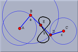 |
| Fig. 7: Constructing a locus |
If you finally select the "Animation" mode again and click on the locus, you will see how the locus was generated.